Photovoltaic System Inverter
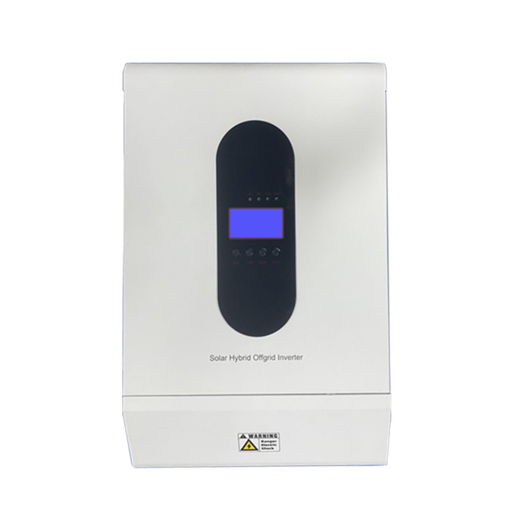
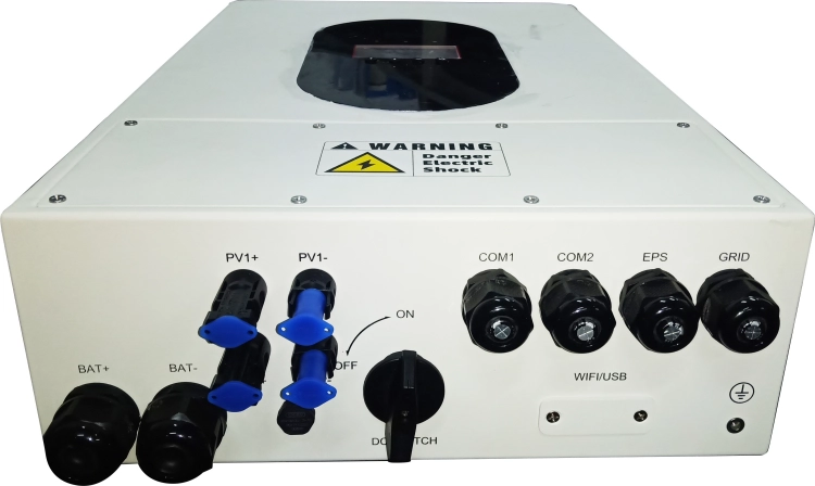
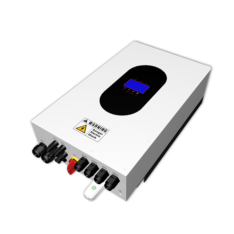
2023-12-20main picture of inverter
In power electronics, the process of converting alternating current (AC) electrical energy into direct current (DC) electrical energy is referred to as rectification, the circuitry that accomplishes the rectification function is referred to as the rectifier circuit, and the device that realizes the rectification process is referred to as the rectifier device or rectifier. In contrast, the process of converting direct current energy into alternating current energy is called inverter, the circuit that accomplishes the inverter function is called inverter circuit, and the device that realizes the inverter process is called inverter equipment or inverter.

The working principle of inverter inverter generally consists of boost circuit and inverter bridge circuit. The boost circuit boosts the DC voltage of the solar cell to the DC voltage required for inverter output control, and the MPPT tracker ensures that the DC power generated by the PV array can be maximized and used by the inverter; the inverter bridge circuit converts the boosted DC voltage into the commonly used frequency AC voltage and current, and the protection function circuit monitors the operating conditions during the inverter operation, and under the abnormal operating conditions, it can trigger the internal relay to protect the inverter. Under abnormal operating conditions, an internal relay can be triggered to protect the internal components of the inverter from damage.
The inverter turns the DC input into AC output through the regular repetition of ON-OFF of the switching elements such as transistors, and then through the high-frequency pulse-width modulation (SPWM), which makes the width of the voltages near the ends of the sinusoidal waveform narrower and that in the center of the sinusoidal waveform wider, and always lets the switching elements move in a certain frequency in a certain direction during the half-cycle, so as to form a pulse waveform (the proposed sinusoidal waveform). Then the pulse wave is passed through a simple filter to form a sine wave of a certain voltage and frequency.
Classification of Inverters
(1) According to the direction of the output power of the inverter, it can be divided into active inverter and passive inverter. For grid-connected photovoltaic power generation system needs active inverter; where the inverter output power transmission to some kind of power load inverter called passive inverter, such as independent photovoltaic system inverter that is passive inverter.
(2) According to the number of phases of the inverter output, it can be divided into single-phase inverter, three-phase inverter and multi-phase inverter.
(3) According to the power size of the inverter, it can be divided into centralized inverter, string inverter and micro inverter.
(4) According to the form of the main circuit of the inverter, it can be divided into single-ended inverter, push-pull inverter, half-bridge inverter and full-bridge inverter.
(5) According to the type of the main switching device of the inverter, it can be divided into thyristor inverter, transistor inverter, field effect inverter and insulated gate bipolar transistor (IGBT) inverter. It can also be summarized as “semi-controlled” inverter and “full control” inverter two categories. The former does not have the ability to turn off, components in the conduction that is the loss of control, so it is called “half-control type”, the ordinary thyristor belongs to this category; the latter has the ability to turn off, that is, no device conduction and shutdown can be controlled by the control pole to control, so it is called “full-control type The latter has the ability of self-shutdown, that is, no device on and off can be controlled by the control pole, so it is called “full-control type”, power field effect transistor and insulated gate double power transistor (IGBT) belong to this category.
(6) According to the frequency of AC power output from the inverter, it can be divided into industrial frequency inverter, medium frequency inverter and high frequency inverter. The frequency of the industrial frequency inverter is 50 to 60 Hz; the frequency of the medium frequency inverter is generally 400 Hz to dozens of kilohertz; high-frequency inverter frequency is generally dozens of kilohertz to megahertz.
(7) According to the DC power source. It can be divided into voltage source inverter (VSI) and current source inverter (CSI). The former has a nearly constant DC voltage and an alternating square wave output voltage; the latter has a nearly constant DC current and an alternating square wave output current.
(8) According to the waveform of inverter output voltage or current, it can be divided into sinusoidal output inverter and non-sinusoidal output inverter.
(9) According to the inverter control mode, it can be divided into frequency modulation (PFM) inverter and pulse width modulation (PWM) inverter.
(10) According to the inverter switching circuit operating mode, can be divided into resonant inverter, fixed-frequency hard-switching inverter and fixed-frequency soft-switching inverter.
(11) According to the inverter current conversion mode, can be divided into load current conversion inverter and self-current conversion inverter.
